The AMD64 Instruction Encoding Format Part 1
Understanding The AMD64 Instruction Encoding Format
For past few days I’ve been working on a personal program/binary analysis tool which I’m calling Katana. I’ve made a simple Elf file loader for now but for it to have more utilities while working, and for me to learn something more, I’ve started working on my own disassembler for Katana. For now I want to support only AMD64 and x86 Instruction formats but in future I want to add support for ARM, MIPS, RISCV etc… I’ve also been doing live streams but the progress is really really slow! I have no guidance and I’m just reading the manuals and working on my own which is quite difficult. But! I won’t complain and I think I’ve found a solution for this! and the solution is to write a blog on the instruction encoding format so that this will act like notes for me.
Please consider this post as a primer before digging into the manual yourself, and this post is in no way a replacement for the detailed manual that you have!
Architecture Programmer Manual
This manual describes all the workings on an AMD64 CPU, like it’s an interface. Whatever’s in the manual must be (assumed) to be true because it is provided by the CPU vendor! There are two versions of AMD64 architecture programmer manual. One is given by Intel and other my AMD itself. I personally find AMD much easier to read because it has less content, better diagrams and it’s precise. Other’s might find Intel to be more precise and complete. Here are the two versions :
- Intel® 64 and IA-32 Architectures Software Developer’s Manual Combined Volumes: 1, 2A, 2B, 2C, 2D, 3A, 3B, 3C, 3D, and 4
- amd64-architecture-programmers-manual-volumes-1-5
Please keep taking reference from this while reading this blog post. But before I can tell you anything about instruction encoding, I have to instroduce you to some basic terms that will be used a lot.
General Instruction Layout
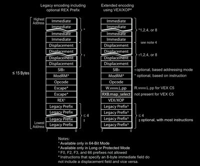
Prefixes
A prefix is a byte that comes at the very beginning of instruction. All prefixes are optional! This means there are instructions that don’t have prefixes at all! They are used to modify the basic instruction’s register/memory size, change segment’s being used, change behaviour by making the instruction repeat multiple times (in string instructions) and give it other magical powers!
There are three types of prefixes :
Legacy Prefixes : These prefixes were present in older architectures also (before
AMD64). There can be maximum of four legacy prefix bytes in an instruction. There are five different types of legacy prefixes.REX Prefix : This is a single byte prefix and there can be maximum one REX prefix in an instruction. They allow access to R-Extended and new registers added to AMD64 architecture. Value of REX prefix ranges from 0x40 to 0x4f. So to detect whether this prefix is a REX prefix or not, we can check whether upper nibble is 0x4 or not.
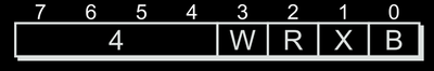
Layout of REX prefix byte (AMD Vol3 Page15) VEX/XOP Prefix : I’ll cover this in a later part maybe, ignore this for now.
I will explain legacy prefixes in more detail later, for now let’s just skim through each name so that you have the names in mind and have an abstract idea of what they do.
Opcode Bytes
An opcode byte is a special byte that uniquely identifies an instruction. For example 0x90 is a special byte that uniquely identifies the nop instruction. Also notice that this instruction won’t need any of the prefix bytes! To uniquely identify an instruction there can be maximum of three opcode bytes and for these we have three different opcode maps. For instructions that have more than three opcode bytes, we have escape sequences.
Escape Sequences
An escape sequence is a unique set of bytes (or a just a single byte) that adds more variety of instructions to the basic instruction set. For example, instructions that have two opcode bytes have 0x0f as their first opcode byte as escape sequence.
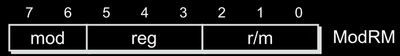
The ModRM Byte
The ModRM byte has three fields.
- Mode field (upper two bits, 0xc0 mask)
- R field (next three bits, 0x38 mask)
- RM field (lower three bits, 0x07 mask)
The ModRM.mod Field
The ModRM.mod field is short for form Mode or to be more precise, it stands for different Register Addressing Modes. A register addressing mode, tells us whether the operands stay in the register or in a memory. Any instruction that takes operands, needs it’s operands to exist somewhere! This can be in either registers (meaning all operands are registers) or atleast one of the operand is a memory operand. We know that there can’t be instructions where all operands (both in case of instructions that take two operands) are memory operands. This means there are two types of addressing modes :
- Register Direct Addressing Mode (
ModRM.mod = 11b) : All operands are in registers. - Register Indirect Addressing Mode (
ModRM.mod != 11b) : Some operands are in registers and some in memory. In case of instructins that take two operands, there will be one operand in a memory location somewhere and other will be in a register.
Examples of instructions in register-direct addressing mode :
xor eax, eaxadd eax, ebxpop ecxand rax, rbxmov eax, 0
Examples of instructions in register-indirect addressing mode :
xor eax, [eax]add dword ptr ds:[eax], ebxmov byte ptr ds:[eax*4 + 0xcafebabe], chmov qword ptr[rbp-0x08], 0
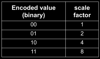
When using indirect addressing mode, we will optionally need a displacement value and optionally an SIB (Scale Index Base) byte. The task of SIB byte is to help us iterate over array like memory regions, given a base value in displacement field, an index register where the index of entry in the array will be stored and a scale value that can be 1, 2, 4 or 8. More on SIB byte later.
The ModRM.r Field
This specifies the register being used in the instruction. Three bits means total of 8 different values. Remind me, how many GPRs are there in x86 instruction set? (eax, ebx, ecx, edx, esi, edi, esp, ebp). Total 8 right? How do we access the extended rXX counterparts of these registers in AMD64 architecture? Take your time and recall what you’ve learned up until now in this post. The answer is by using REX prefix. There’s a specific bit (REX.W) in the lower nibble of REX prefix that is used in combination to this ModRM.r field and another bit in REX (REX.B) to allow it 16 different registers . If REX.R is zero then you won’t be able to access the complete R-Extended registers but instead lower parts like lower double-word or just a word. The REX.B bit is placed as the most significant bit in front of ModRM.r field to create the whole field of 4 bits and hence get 16 different values to access 16 different GPRs.
The ModRM.rm Field
This specifies the register/memory operand based on the register addressing mode we talked about. If the mode is register direct addressing mode then this will refer to a register, else a memory operand. Here instead of REX.W and REX.R, there is REX.X and REX.B respectively. The rest of the working is pretty much same as ModRM.r field except a few places that we will discuss later.
The Combination Of REX and ModRM Byte
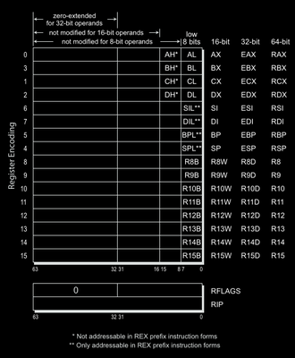
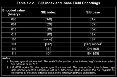
As I mentioned, REX byte is used in combination with ModRM byte to give access to all 16 R-Extended registers. Before we continue, I’d like to give you values of the ModRM.r and ModRM.r/m field that index different registers.
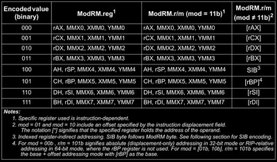
Please ignore the fourth column for now and only refer to first, second and third one. For given 8 values using only ModRM.r or ModRM.rm field and no REX prefix byte, we can have access to only these registers, but if we flag the REX.R bit as 1 then we 8 more different values which are used to index registers r8 to r15. There are instructions that access only a part of these registers, like only the lower byte, or word, or double word. In those cases the REX.W prefix will be ignored. REX.W prefix is taken into account only where it’s possible to increaase the size of registers to their maximum.
So, let’s say the REX.R bit is flagged and the ModRM.r field is set to 0, then the effective value (which is 8) will index to r8 register and it’s smaller parts depending on the instruction. For example 00 and 03 are two instruction opcodes that belong to the ADD instruction family.
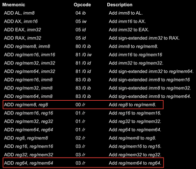
Don’t pay attention to the specific opcodes and just pay attention to the first byte in opcode and the size of operands in the instruction. I’ll now give a few examples here and let you figure out how this work
For adding r8b (lower byte of r8 register) and al (lower byte of rax register), and storing the result back to al, we have the instruction : add al, r8b which assembles to 44 00 c0.
For adding r15 and rax and storing result back to r8, we have instruction : add rax, r15 which assembles to 4c 03 f8.
Having problems assembling this? We’ll we’re writing a disassembler, so maybe first try decoding the opcodes I gave you. First try to identify whether there is a REX prefix or not, then identify the opcode, then decode the value of ModRM fields and try to get operands.
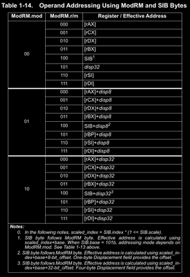
Now, if you are a keen observer, then you might have noticed something here! We’ve never specified the order in which the operands will appear! This operands are specified by the ModRM byte right? Where did we specify the order in which the operands encoded in this ModRM byte will be? This is given by the instruction you are using! If the operand in the instruction mnemonic is written as regXX/memXX where XX is the size of register or memory then that means that operand is indexed using the ModRM.rm field. For operand encoded just as regXX we have ModRM.r field. Obviously this means the extended versions of these fields also if REX prefix is present. This means while writing disassembler, you have to take references from these tables also! Phew!!
The SIB (Scale Index Base) Byte
This is a special form of register-indirect memory addressing for accessing an array like memory region.
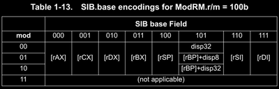
An SIB byte is present only if the mode is register-indirect and ModRM.rm value is 100b.
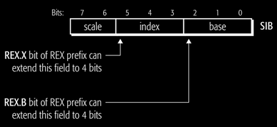
Then the SIB.index field is used to specify the index of register containing the index into array and the SIB.base field is used to specify the index of register containing base address of this register-indirect addressing mode.
Note that here ModRM.rm is fixed to 100b so all index is done by SIB byte. For second operand, ModRM.r can index to other registers. Due to this configuration, the REX.X and REX.B bits were given to extend this SIB.base and SIB.index fields.
As examples
03 84 c1 00 00 00 00decodes toadd eax, dword ptr ds:[rcx+rax*8]in 64 bit mode. This is because for84, we haveModRM.mod = 10bandModRM.r = 00bandModRM.rm = 100band then sinceModRM.rmis100b, we have anSIBbytec1which after you decode, you’ll getSIB.scale = 11b,SIB.index = 000bandSIB.base = 001b. Refer to the above tables and try to decode this!03 84 c2 00 00 00 00decodes toadd eax, dword ptr ds:[rdx+rax*8]03 84 c3 00 00 00 00decodes toadd eax, dword ptr ds:[rbx+rax*8]03 84 c3 00 00 00 01decodes toadd eax, dword ptr ds:[rbx+rax*8+0x1000000]48 03 84 c3 00 00 00 01decodes toadd rax, qword ptr ds:[rbx+rax*8+0x1000000]4c 03 84 c3 00 00 00 01decodes toadd r8, qword ptr ds:[rbx+rax*8+0x1000000]4c 03 84 e3 00 00 00 01decodes toadd r8, qword ptr ds:[rbx+0x1000000]4c 03 84 d3 00 00 00 01decodes toadd r8, qword ptr ds:[rbx+rdx*8+0x1000000]
The Legacy Prefixes In Combination With REX and ModRM
Legacy prefixes are of five types and each type has specific byte assigned. Comparing the first few bytes of instruction with these special bytes, we can check whether this byte is a legacy prefix byte or not.
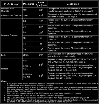
The Operand Size Override Prefix (0x66)
This prefix is used to override and select the non default operand size. If REX prefix byte is present along with this prefix byte then, REX is always given preference! Also, this byte has some other meanings too which is used to extend the instruction set. More on that in later parts of this post (series).
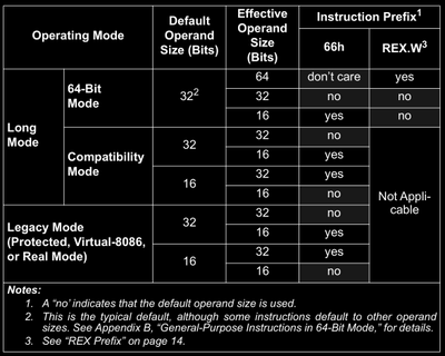
Take a look at this table and closely understand the meaning and then try to decode/assemble the following opcodes/instructions.
66 03 f866 03 c066 03 ca66 00 ca00 ca00 f8add al, aladd al, dhadd dh, al
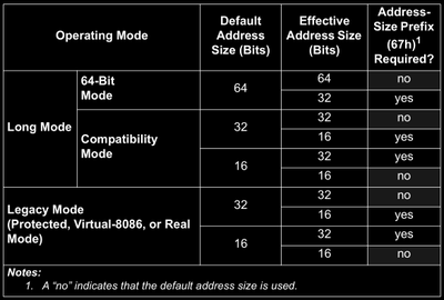
The Address Size Override Prefix (0x67)
This prefix is used to change the address size when accessing an address. For example in instructions mov byte ptr ds:[rax] and mov qword ptr ds:[rax] has different address sizes. This is also changing the default address size just like address size override.
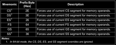
The Segment Override
This is used to override default segment being used when getting values from a memory address. For example, you can use address size override prefix to change from ds to cs segment, like mov word ptr ds:[rdi*4 + base] to mov word ptr cs:[rdi*4+base].
Similarly you can take reference for LOCK and REP, REPE/REPZ and REPNE/REPNZ prefixes from the manual.
Immediate and Displacement Fields
These two values depend on the instruction you’re trying to decode. You can refer to the instruction reference in the manual. If the instruction wants an immediate value as one of it’s operands, then it’ll surely be there!
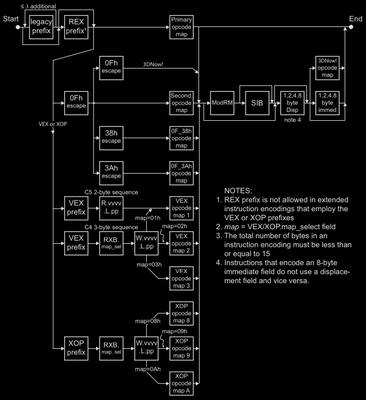
The Instruction Decoding Algorithm
This writeup is no replacement for the 3000+ pages architecture manual given by the CPU vendor themselves to you. Ending this post with an awesome diagram from the manual itself to help you understand step wise how to decode the AMD64 instruction.
As promised, I did a writeup for introducing you to the AMD64 Instruction Encoding formathttps://t.co/KVOBKG5KLb
— Siddharth Mishra (@brightprogramer) March 1, 2023
Siddharth Mishra
Computer Science Enthusiast
Building and breaking into systems to learn them inside out!